
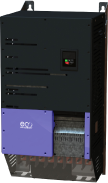
Преобразователь частоты
Преобразователи частоты для насосов и вентиляторов
0.75-250 кВт/ 1-350 л.с.
Вход 200-600В 1 фаза или 3 фазы
Спецификации
IP20
SIZE
Height
Width
Depth
Weight
Packaged Weight
Fixings

2
221
110
185
1.8
1.9
4 x M4

3
261
131
205
3.5
3.5
4 x M4

4
418
160
240
8.1
N/A
-

5
486
222
260
17
N/A
-
8
995
482
480
128
N/A
N/A
IP66
SIZE
Height
Width
Depth
Weight
Packaged Weight
Fixings

2
257
188
260
5.5
N/A
4 x M4

3
310
211
273
8.5
N/A
4 x M4
IP55
SIZE
Height
Width
Depth
Weight
Packaged Weight
Fixings

4
450
171
252
12
N/A
4 x M8
5
540
235
270
23.1
N/A
4 x M8
6
865
330
330
55
56.5
4 x M10
7
1280
330
360
89
97
4 x M10
Technical Specifications
Input Ratings
| Supply Voltage | 200 – 240V ± 10% 380 – 480V ± 10% 500 – 600V ± 10% |
|
| Supply Frequency | 48 – 62Hz | |
| Displacement Power Factor | > 0.98 | |
| Phase Imbalance | 3% Maximum allowed | |
| Inrush Current | < rated current | |
| Power Cycles | 120 per hour maximum, evenly spaced | |
Output Ratings
| Output Power | 230V 1Ph. Input: 0.75–2.2kW (1–3HP) 230V 3Ph. Input: 0.75–75kW (1–100HP) 400V 3Ph. Input: 0.75–250kW 460V 3Ph. Input: 1–350HP 575V 3Ph. Input: 0.75–110kW (1–150HP) |
|
| Overload Capacity | 110% for 60 seconds 165% for 4 seconds |
|
| Output Frequency | 0 – 250Hz, 0.1Hz resolution | |
| Typical Efficiency | > 98% | |
Ambient Conditions
| Temperature | Storage : −40 to 60°C Operating : −10 to 50°C |
|
| Altitude | Up to 1000m ASL without derating Up to 2000m maximum UL approved Up to 4000m maximum (non UL) |
|
| Humidity | 95% Max, non condensing | |
| Vibration | Conforms to EN61800-5-1 2007, IEC 60068-2-6 | |
Enclosure
| Ingress Protection | IP20, IP55, IP66 | |
Programming
| Keypad | Built-in keypad as standard Optional remote mountable keypad |
|
| Display | Built-in multi language OLED (IP55 & IP66) 7 Segment LED (IP20) |
|
| PC | OptiTools Studio | |
Control Specification
| Control Method | Eco Sensorless Vector Open Loop Permanent Magnet Vector Open Loop BLDC Vector Open Loop Synchronous Reluctance Vector |
|
| PWM Frequency | 4 – 32kHz Effective | |
| Stopping Mode | Ramp to stop: User Adjustable 1–600 secs Coast to stop |
|
| Braking | AC Flux Braking | |
| Skip Frequency | Single point, user adjustable | |
| Setpoint Control | Analog Signal | 0 to 10 Volts / 10 to 0 Volts −10 Volts to +10 Volts 0 to 20mA / 20 to 0mA 4 to 20mA / 20 to 4mA |
| Digital | Motorised Potentiometer (Keypad) Modbus RTU BACnet MS/TP |
|
Fieldbus
| Built in | BACnet MS/TP | BACnet Application Specific Controller 9.6 - 76.8 kbps selectable Data Format: 8N1, 8N2, 8O1, 8E1 |
| Modbus RTU | 9.6 - 115.2 kbps selectable Data Format: 8N1, 8N2, 8O1, 8E1 |
I/O Specification
| Power Supply | 24 Volt DC, 100mA, Short Circuit Protected 10 Volt DC, 10mA for Potentiometer |
|
| Programmable Inputs | 5 Total as standard (optional additional 3) 3 Digital (optional additional 3) 2 Analog / Digital selectable |
|
| Digital Inputs | Opto - Isolated 8 – 30 Volt DC, internal or external supply Response time < 4ms |
|
| Analog Inputs | Resolution: 12 bits Response time: < 4ms Accuracy: < 1% full scale Parameter adjustable scaling and offset |
|
| PTC Input | Motor PTC / Thermistor Input Trip Level : 3kΩ |
|
| Programmable Outputs | 2 Total 1 Analog / Digital 1 Relay |
|
| Relay Outputs | Maximum Voltage: 250 VAC, 30 VDC Switching Current Capacity: 5A |
|
| Analog Outputs | 0 to 10 Volts / 10 to 0 Volts 0 to 20mA / 20 to 0mA 4 to 20mA / 20 to 4mA |
|
Application Features
| PID Control | Internal PID Controller Multi Setpoint Select Standby / Sleep Mode Boost Function |
|
| Fire Mode | Bidirectional Selectable Speed Setpoint (Fixed / PID / Analog / Fieldbus) |
|
| Load Monitoring | High Current Protection (Fan / Bump Blocked) Low Current Protection (Broken Belt / Shaft) Pump Blockage Detection with Cleaning |
|
| Duty / Assist / Standby | Built-in Multi Pump Support Autotmatic Changeover on Fault Automatic Changeover on Run Time Fully Redundant |
|
Pump Control Features
| Pump Blockage Detection | Pump load monitoring with autotune function, user configurable | |
| Pump Cleaning | Adjustable Bi-Directional Pump Cleaning Cycle operation | |
| Multi-pump Control | Control of fixed speed assist pumps (with cascade control module) Control of Duty, Assist and Standby variable speed pumps via internal Master – Slave network |
|
| Pump Stir | Automatic pump stir to prevent sediment build-up | |
Maintenance & Diagnostics
| Fault Memory | Last 4 Trips stored with time stamp | |
| Data Logging | Logging of data prior to trip for diagnostic purposes: Output Current Drive Temperature DC Bus Voltage |
|
| Maintenance Indicator | Maintenance Indicator with user adjustable maintenance interval Onboard service life monitoring |
|
| Monitoring | Hours Run Meter Resettable & Non Resettable kWh meters Cooling Fan Run Time |
|
Standards
| Low Voltage Directive | 2014/35/EU | |
| EMC Directive | 2014/30/EU | |
| Additional Conformance | UL, cUL, EAC, RCM | |
| Harmonic Currents | IEC61000-3-12 | |
| Environmental Conditions | Designed to meet IEC 60721-3-3, in operation: IP20 Drives: 3S2/3C2 IP55 & 66 Drives: 3S3/3C3 |
|
Connection Diagram

| Terminal | Function | Default Setting |
|---|---|---|
| 1 | 24 Volt DC Output, 100mA max / 24 Volt DC Input | |
| 2 | Digital Input 1 | Drive Enable |
| 3 | Digital Input 2 | Analog/Preset Speed 1 Select |
| 4 | Digital Input 3 | Local/Remote Reference Select |
| 5 | +10 Volt Power Supply 5mA | |
| 6 | Analog Input 1 | Local Speed Reference |
| 7 | 0 Volt | |
| 8 | Analog Output 1 | Motor Speed |
| 9 | 0 Volt | |
| 10 | Analog Input 2 | Remote Speed Reference |
| 11 | Analog Output 2 | Motor Current |
| 12 | Safe Torque Off Input | |
| 13 | Safe Torque Off Input | |
| 14 | Output Relay 1 | Drive Healthy/Fault |
| 15 | ||
| 16 | ||
| 17 | Output Relay 2 | Drive Running |
| 18 | ||