
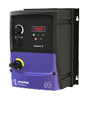
Преобразователь частоты
Преобразователи частоты общего назначения
0.37-22 кВт/ 0.5-30 л.с.
Вход 110-480В 1 фаза или 3 фазы
Спецификации
IP20
SIZE
Height
Width
Depth
Weight
Packaged Weight
Fixings

1
173
83
123
1
-
4 x M5

2
221
110
150
1.7
-
4 x M5

3
261
131
175
3.2
-
4 x M5

4
420
171
212
9.1
-
4 x M8
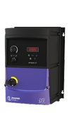
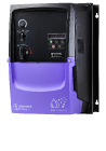
IP66 Outdoor
SIZE
Height
Width
Depth
Weight
Packaged Weight
Fixings

1
232
161
155
2.1
-
4 x M4
2
257
188
180
3
-
4 x M4
3
310
210.5
215
5
-
4 x M4
4
380
210.5
235
7
-
6 x M4
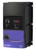
IP66 Indoor
SIZE
Height
Width
Depth
Weight
Packaged Weight
Fixings

1
232
161
179
3.1
-
4 x M4

2
257
188
187
4.1
-
4 x M4
3
310
210.5
252
7.6
-
4 x M4
Technical Specifications
Input Ratings
| Supply Voltage | 100 – 115V ± 10% 200 – 240V ± 10% 380 – 480V ± 10% |
|
| Supply Frequency | 48 – 62Hz | |
| Displacement Power Factor | > 0.98 | |
| Phase Imbalance | 3% Maximum allowed | |
| Inrush Current | < rated current | |
| Power Cycles | 120 per hour maximum, evenly spaced | |
Output Ratings
| Output Power | 110V 1 Ph Input: 0.5–1.5HP (230V 3 Ph Output) 230V 1 Ph Input: 0.37–4kW (0.5–5HP) 230V 3 Ph Input: 0.37–11kW (0.5–15HP) 400V 3 Ph Input: 0.75–22kW 460V 3 Ph Input: 1–30HP |
|
| Overload Capacity | 150% for 60 Seconds 175% for 2.5 seconds |
|
| Output Frequency | 0 – 500Hz, 0.1Hz resolution | |
| Typical Efficiency | > 98% | |
Ambient Conditions
| Temperature | Storage: -40 to 60°C Operating: -10 to 40°C |
|
| Altitude | Up to 1000m ASL without derating Up to 2000m maximum UL approved Up to 4000m maximum (non UL) |
|
| Humidity | 95% Max, non condensing | |
| Vibration | Conforms to EN61800-5-1 | |
Enclosure
| Ingress Protection | IP20, IP66 | |
Programming
| Keypad | Built-in keypad as standard Optional remote mountable keypad |
|
| Display | 7 Segment LED | |
| PC | OptiTools Studio | |
Control Specification
| Control Method | Sensorless Vector Speed Control PM Vector Control BLDC Control Synchronous Reluctance |
|
| PWM Frequency | 4 – 32kHz Effective | |
| Stopping Mode | Ramp to stop: User Adjustable 0.1 – 600 secs Coast to stop |
|
| Braking | Motor Flux Braking Built-in braking transistor (not frame size 1) |
|
| Skip Frequency | Single point, user adjustable | |
| Setpoint Control | Analog Signal | 0 to 10 Volts 10 to 0 Volts 0 to 20mA 20 to 0mA 4 to 20mA 20 to 4mA |
| Digital | Motorised Potentiometer (Keypad) Modbus RTU CANopen |
|
Fieldbus
| Built in | CANopen | 125–1000 kbps |
| Modbus RTU | 9.6–115.2 kbps selectable |
I/O Specification
| Power Supply | 24 Volt DC, 100mA, Short Circuit Protected 10 Volt DC, 10mA for Potentiometer |
|
| Programmable Inputs | 4 Total 2 Digital 2 Analog / Digital Selectable |
|
| Digital Inputs | 8 – 30 Volt DC, internal or external supply Response time < 4ms |
|
| Analog Inputs | Resolution: 12 bits Response time: < 4ms Accuracy: ± 2% full scale Parameter adjustable scaling and offset |
|
| Programmable Outputs | 2 Total 1 Analog / Digital 1 Relay |
|
| Relay Outputs | Maximum Voltage: 250 VAC, 30 VDC Switching Current Capacity : 6A AC, 5A DC |
|
| Analog Outputs | 0 to 10 Volt | |
Application Features
| PI Control | Internal PI Controller Standby / Sleep Function |
|
| Fire Mode | Bidirectional Selectable Speed Setpoint (Fixed / PI / Analog / Fieldbus) |
|
Maintenance & Diagnostics
| Fault Memory | Last 4 Trips stored with time stamp | |
| Data Logging | Logging of data prior to trip for diagnostic purposes: Output Current Drive Temperature DC Bus Voltage |
|
| Monitoring | Hours Run Meter | |
Standards
| Low Voltage Directive | Adjustable speed electrical power drive systems. EMC requirements |
|
| EMC Directive | 2014/30/EU Cat C1 according to EN61800-3:2004 |
|
| Machinery Directive | 2006/42/EC | |
| Conformance | CE, UL, RCM | |
| Environmental Class | 3C3/3S3 conformal coated PCBs | |
Connection Diagram
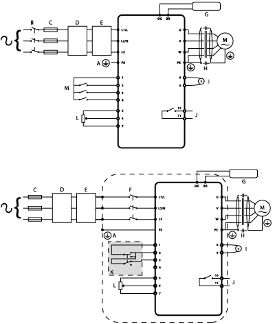
| Terminal | Function | |
|---|---|---|
| A | Protective Earth (PE) Connection | |
| B | Incoming Power Connection | |
| C | Fuse / Circuit Breaker Selection | |
| D | Optional Input Choke | |
| E | Optional External EMC Filter | |
| F | Internal Disconnect / Isolator | |
| G | Optional Brake Resistor | |
| H | Motor Connection | |
| I | Analog Output | |
| J | Relay Output | |
| K | Using the REV/0/FWD Selector Switch (Switched Version Only) | |
| L | Analog Inputs | |
| M | Digital Inputs | |